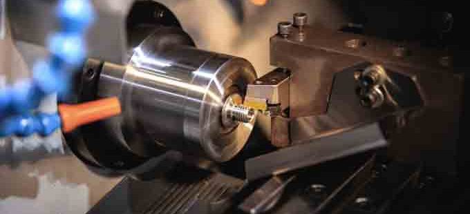
PCD end milling is a method of cutting a metal or plastic part using a diamond tool. It uses a high-temperature, high-pressure process to create the diamond vein that forms the cutting edge. This method is expensive and requires special tooling, but can be durable for a long time. PCD is also known as amorphous diamond or nanocomposite PVD.
Cutting parameters
A PCD end mill cutter is a rotary cutting tool with a blade made of polycrystalline diamond or tungsten carbide. The PCD material has a high hardness and a low friction coefficient. The carbide layer provides mechanical support for the diamond layer and increases the tool’s bending strength. Various shapes of PCD milling cutters can be made.
Cutting parameters for PCD end milling must be optimized to achieve good surface finish. The optimum cutting parameters include spindle speed, feed rate, and depth of cut. Various methods for analyzing the effect of cutting parameters include Taguchi orthogonal arrays, signal-to-noise ratio, and analysis of variance.
Material removal rate
The material removal rate of pcd end mills depends on a variety of factors, including axial and radial depth of cut. The cutting force is a major factor, but tool flank wear also plays a role. The amount of material removed by a PCD mill depends on the radial depth of cut and the tool’s axial speed.

In this study, PCD end mills with corner radius were used for precision milling of zirconia ceramics, with Vickers hardness of HV 1180. In addition, high-performance milling experiments were performed to understand the characteristics of the machined surfaces. Based on these experiments, the author proposes a strategy to improve material removal rates and machined surface quality.
Tool geometry
Tool geometry for PCD end milling is an important process parameter. The design of the cutting edge influences the overall process and its output. In geometry I, the cutting edge was flat, and the feed per tooth was 0.3 mm. Increasing the feed per tooth would cause marks on the back side of the trajectory. In geometry II, the cutting edge is curved. This reduces the source of wear and increases tool life.
Cutting speed is an important factor for the best results. The cutting speed is usually determined by using the French Standard procedure VF-E66-520-1. The cutting speed is determined by looking at curves for different insert parameters.
Tool type
PCD end mills are brazed-tipped metal work tools, suitable for cutting cast aluminum and composite components. The PCD insert resists abrasion wear and increases the tool life of this tool. A PCD end mill requires a high spindle speed and rigid tooling setup to obtain optimal results. ASIME, a ISO-certified cutting tool manufacturer, can supply end mills with high-quality PCD cutting edges to meet the specific needs of specific applications.
The PCD end milling tool type has many advantages over its counterparts. This cutting tool type is able to process a wide variety of materials, including CFRP parts, engine cases, and composites. Unlike other types of end mills, this type of tool is extremely durable, and can last for a long time.
Tool size
PCD end milling is a type of milling process that utilizes the use of a ball-end mill with a sharp cutting edge. A PCD ball-end mill can produce large negative rake angles and a sharp cutting edge. A PCD end mill can be used in a 0deg or -15deg rake angle.
Summary:
The standard PCD end mill has a diameter of up to 50 mm. These tools can cut up to 50 mm deep and feature a wide range of rake angles and center cutting geometries. The tools can be purchased with a short lead time. They are also designed for rough and finish milling operations.
- Growing IT Sector in Prague: What Businesses Need to Know? - November 18, 2024
- How to Choose the Perfect Luxury Hotel in Prague for Your Stay? - November 18, 2024
- Why Skincare Product Ingredients Matter for Lasting Results? - November 3, 2024

